Our flow meters provide accurate measurement of liquid flow across a wide variety of commercial and residential applications including process control, water resource management, and energy consumption. Ultrasonic flowmeters have many advantages over conventional mechanical or magnetic flowmeters, specifically:
They don’t have moving parts and therefore require minimal, if any maintenance.
Unlike traditional flowmeters, they don’t introduce obstructive components into the pipe, and therefore eliminate any interference to the flow profile and pressure. In fact, clamp on ultrasonic flowmeters require zero pipe work and never come in contact with the liquid at all.
Ultrasonic flowmeters use one of four basic measurement principles. They are:
1. Transit-time Technology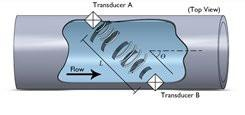 One of the most reliable and time tested measurement principles is Transit-time flow measurement. A typical transit-time ultrasonic flowmeter system utilizes one pair of transducers that function as both the ultrasonic transmitter as well as the receiver. We will explore Transit-time flow measurement in greater detail in the next section.
2. Ultrasonic Doppler Technology
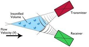
In Doppler style flowmeters, two ultrasonic transducers are employed in the system. One transmits a continuous ultrasonic wave into the flow. The other transducer receives the ultrasonic wave scattered from suspending particles (or targets). The received wave has a frequency shift comparing with the transmitted one. This shift is the so-called Doppler frequency shift, which is directly proportional to the flow velocity. Therefore, by detecting the Doppler frequency, we are able to derive the flow velocity. The flow rate of the pipe liquid is obtained by computing the product of the velocity and the cross-section area of the pipe.
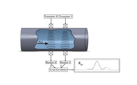
3. Cross-Correlation Measurement Technology
The Cross-Correlation principle provides accurate and reliable flow measurement. A turbulent flow has a cascade structure of eddies. Along the flow, the characteristics of those structures do not change much within a certain distance, called the Correlation Length. It is by tracking particles along this length, that Cross-Correlation measurement is achieved.
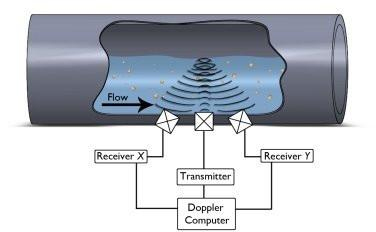
4. Acoustic Doppler Velocity Profiling Technology
Three acoustic transducers are installed as shown in the left figure. The center one is usually a narrow-beam transducer. It transmits a burst of sound pulses with a certain Pulse Repetition Frequency (PRF). The other two are large angle transducers. They receive the ultrasonic wave scattered from suspending particles (or targets) of the water column insonified by both the transmitting and receiving sound beams. By using a pulse-to-pulse algorithm, we are able to obtain the Doppler frequency shift at two directions, from which a 2D velocity profile can be formed.
One of the most widely accepted ultrasonic methods – Transit-time flow measurement– utilizes two ultrasonic transducers that function as both the ultrasonic transmitter and receiver. The flow meter operates by alternately transmitting and receiving a burst of sound energy between the two transducers and measuring the transit time that it takes for sound to travel between the two transducers. The difference in the transit time measured is directly and exactly related to the velocity of the liquid in the pipe.
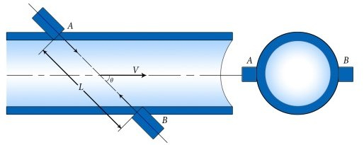
To be more precise, let's assume that Tdown is the transit-time (or time-of-flight) of a sound pulse traveling from the upstream transducer A to the downstream transducer B, and Tup is the transit-time from the opposite direction, B to A. The following equations hold:
Tdown = ( D / sinq ) / ( c + V*cosq ), (1)
Tup = ( D / sinq ) / ( c - V*cosq ), (2)
Where c is the sound speed in the liquid, D is the pipe diameter and V is the flow velocity averaged over the sound path. Solving the above equations results in:
V = ( D / sin2q ) * ∆T / (Tup * Tdown), (3)
Where ∆T = Tup - Tdown. Therefore, by accurately measuring the upstream and downstream transit-time Tup and Tdown, we are able to obtain the flow velocity V. Subsequently, the flow rate is calculated as following:
Q = K *A* V, (4)
Where A is the inner cross-section area of the pipe and K is the instrument coefficient. Usually, K is determined through calibration.
From equations (3) and (4), we see that the measurement results, V and Q, are independent of fluid properties, pressure, temperature, pipe materials, etc. The sound speed term does not appear in the final equations. These characteristics, plus large turn-down ratio, no pressure drop, no moving parts, no disturbance to the flow and many other features, make ultrasonic transit-time flowmeter extremely attractive.
Transducers of either type can be used in Transit-time measurement; clamp-on type or wetted type. The wetted type can be further categorized into insertion type and flow cell (or spool piece) type. A brief comparison among those types can be found in the below diagram.
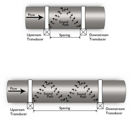
The transducers can be mounted in three ways: Z-method, V-method and W-method. With the Z-method, the two transducers are mounted on opposite sides of the pipe (see top figure below) and the sound pulse crosses the pipe flow once. This method is usually used for larger pipe sizes, above 12".
With V-method, the two transducers are mounted on the same side of the pipe and the sound pulse crosses the pipe flow twice. This is the most commonly used installation method, and is applied with pipe sizes from 1" through approximately 12".
With W-method (see bottom figure below), the two transducers are mounted on the same side of the pipe. However, the spacing between the two transducers is doubled when compared with the V-method. The sound pulse is bounced twice from the other side of the pipe, thus intercepting the flow four times. This method is used for small pipe applications, usually less than 1 1/2", for better accuracy.
It should be mentioned that the actual implementation of Transit-time flow measurement solutions are very complex and introduce a variety of challenges including: